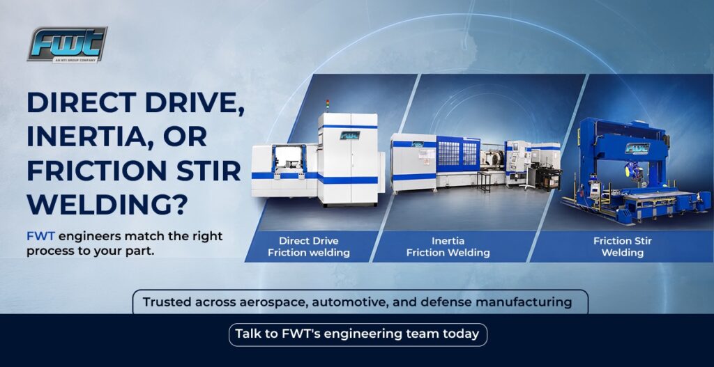
One part. One optimised friction welding process. Get that match wrong and you either pay for more machine than the job needs, or you ask a process to do something it was never built to do. Get it right, and the joint outperforms almost anything traditional welding can produce – at a lower cost per part once volumes climb. The question buyers usually bring to FWT is not whether friction welding will work. It is which friction welding process fits their part, and that is the question FWT engineers answer every day by working hands-on across all three technologies rather than steering every job toward whichever process a single machine happens to cover.
There are three main options, and each one earns its place for different reasons. Direct Drive, Inertia, and Friction Stir all fall under the same solid-state joining family, but the way each variation of the friction welding process welds a joint is different enough that the choice matters from the very first design review. Because FWT has expertise across all three, the process a customer walks away with is chosen to fit the part, not to fit whatever equipment happens to be available.
Direct Drive: The Original Friction Welding Process
Direct Drive is the original friction welding process, and it remains the workhorse for many manufacturers. One part is spun by a motor at a controlled speed while the other is pushed against it under axial force. Once the interface reaches the right temperature, the motor is stopped and a forging force completes the bond. Because speed and force are independently controlled throughout the cycle, Direct Drive gives engineers fine control over the weld, which makes this friction welding process a strong fit for parts with tighter metallurgical requirements or more complex joint geometries. FWT’s team turns to Direct Drive most often when a part’s material combination demands that level of control, such as a heat cycle that has to be managed carefully to join dissimilar metals.
Inertia Welding: Built for High-Volume Repeatability
Inertia welding is a subset of the same Rotary family as Direct Drive, but it stores energy differently. A flywheel is spun up to a set speed, disengaged from its drive motor, and then the stored kinetic energy is what drives the weld as the flywheel decelerates against the stationary part. The friction welding process is prised for its repeatability and simplicity. Once a flywheel mass and speed are dialed in for a given part, that same setup produces a consistent joint run after run, which is exactly why Inertia welding scales so well for high-volume production or components like pistons, axles, and valve bodies.
Friction Stir Welding: Ideal for Large Panels and Structures
Friction Stir Welding (FSW) works on a different principle entirely and is often the preferred friction welding process for joining large panels, extrusions, and structures. A rotating, non-consumable pin tool is plunged into and moved along the joint line between two components, most often plates or extrusions, softening the material through friction and mechanically stirring it into a solid bond without melting it. Friction Stir has become especially important in rail, automotive, and aerospace manufacturing where aluminium panels, battery trays, and other flat or long joints need a strong, low-distortion weld that traditional welding struggles to deliver cleanly. FWT’s applications team works through tool design and travel speed for each new FSW joint since those parameters shift with panel thickness and alloy.
Comparing the Three Processes at a Glance
| Process | Ideal Geometry | Typical Production Volume | Common Applications | Key Advantages |
| Direct Drive | Round parts that can be chucked and rotated | Low-to-mid volume; prototype through mid-run production | Pump shafts, automotive and defence components, bimetal cutting tools | Precise control of speed and force for fine-tuned heat input and tighter metallurgical control |
| Inertia | Round parts that can be chucked and rotated | High-volume, highly repeatable runs | Diesel pistons, axles, valve bodies, drill pipe and jet engine compressor rotors | Simple, repeatable setup once flywheel mass and speed are dialed in; strong run-to-run consistency |
| Friction Stir | Flat plates, extrusions, and long or curved seams that cannot rotate | Scales from low-to-high volume, especially for long, continuous seams | EV battery trays, aerospace fuel tanks, railcar bodies, aluminium panels | Low-distortion, strong joints in materials that are difficult to weld traditionally |
How to Choose the Right Process for Your Part
Geomtery is the first filter. If both sides of the joint are round or can be chucked and rotated, Direct Drive or Inertia are almost always the right friction welding process to evaluate first. If the joint is a stright or curved seam between two flat or extruded sections, Friction Stir is usually the better starting point. Production volume and consistency requirements com next. Inertia tends to win on high-volume repeatability, and it also provides more accuracy when a part needs nuanced control over heat input and upset, such as with dissimilar metals or unusual cross sections. Those are starting points, not hard rules; a round part with an usual cross sectionor a history of cracking under a previous joining method might still be better suited to Direct Drive’s finer control than by Inertia’s simplicity, and working through that kind of judgment call is exactly what FWT’s engineering review is for.
Material combination matters just as much as geometry. Some pairings, like certain bimetal cutting tool blanks, are proven candidates for a Rotary Friction Welding process while other, like long aluminium extrusions in an EV battery tray, are far better suited to Friction Stir. Wall thickness, part diameter, and whether the two materials have been welded together before are all factors into which friction welding process FWT’s engineers will recommend.
Cost is the other half of the equation. Choosing the wrong friction welding process usually shows up as either an oversized machine investment or a part that needs constant rework to hit spec. A compact Direct Drive welder and a heavy-duty Inertia machine solve very different problems, and FWT builds across that entire range so the recommendation is based on the part.
Real parts make the trade-offs easier to picture. Drill pipe and tool joints in oil and gas usually favor Direct Drive or Inertia since the geometry is round and the joint needs to survive years of torque and vibration. Axles, shafts, and valve bodies across automotive and industrial equipment are classic Inertia work, prised for how consistently the process repeats across thousands of identical parts. Aerospace fuel tanks, EV battery enclosures, and long aluminium extrusions lean toward Friction Stir where a continuous seam and minimal distortion matter more than rotational symmetry. Drawing on decades of friction welding experience across industries and applications, FWT’s engineers evaluate part geometry, material compatibility, joint requirements, and production objectives early in the design process identifying the most viable welding approach well before trial welds begin.
Work with FWT’s Engineering Team
This is exactly the kind of decision that benefits from an outside set of eyes before capital gets committed. FWT’s engineering team reviews part prints, material specifications, and production targets, then recommends the friction welding process and machine class that actually fits, along with sample welding trials to prove it out before a full production order is placed.
If you are still narrowing down which friction welding process suits your next part, explore FWT’s full machine range across Direct Drive, Inertia, and Friction Stir welders, or run your materials through the online compatibility checker for a fast first read. Either way, talk to an expert before locking in a part design since the right process choice made early saves both time and money later in the program.